| SHDesigns: Embedded Systems Design, Consulting and Developer Resources | Page hits: |
 Revised 5-7-2005: Added LED and
notes to schematic.
Revised 5-7-2005: Added LED and
notes to schematic.
The above schematic can be viewed in Adobe PDF here: gcellchg.pdf (right-click on link and select "save link as" to save.)
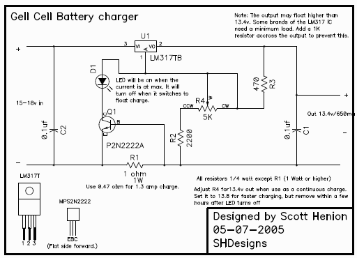
The above circuit will charge any 12v Gell Cell. Maximum current is about 650 milliamps. This charger will not overcharge a gell cell. In fact, it can be left on indefinately. This is an improved version of the float charge method described by Panasonic: http://www.panasonic.com/industrial/includes/pdf/Panasonic_VRLA_ChargingMethods.pdf
Power can be from any 15-18v supply. I use an old 12v/1A wall transformer (outputs about 17v with no load.)
How it works:
This circuit controls both the current and the charge voltage. U1 along with resistors R2, R3 and R4 generate a 13.4v output. This is the voltage specified by gell cell manufacturers as a "constant charge voltage." At 13.4v the batt will never overcharge. Some batteries specify 13.6 to 14.7 volts, but testing has shown that many batts will leak if float charging at this voltage *. U1 can only carry up to 1.5 amps and is limited by its heat dissipation. Q1 and R1 limit the current to about 0.65 amps. This limits the current to protect U1 and the battery from over current.
* Panasonic batteries may be able to withstand this voltage. My work with UPS designs has had terminals of several brands corrode off of batteries if the voltage was set higher than 13.4v.
Notes:
A 7Ah Gel Cell will be close to fully charged in a few hours after a normal days use. Leaving the battery on the charger will NOT overcharge it. In fact it will maintain a battery forever.
Assembly:
The entire circuit can be constructed on a small perf board 1" square or so. U1 (LM317) must have a heat sink; a small piece of aluminum will do. There are many heat sinks available. The size of the heat sink depends on the input voltage. Note: the case of U1 is connected to pin 3, so the heatsink must be isolated from any other parts of the circuit. An insulator (TO-220 type) can be used to isolate the case from the heatsink if needed (i.e. bolting U1 to the case as a heatsink.) U1 should not get too hot to touch.
Adjust R4 for 13.4 to 13.5 volts out with no load.
Parts (Radio Shack part numbers given.):
| Description | RS part # | |
| U1 | LM317T adj. regulator | 276-1778 |
| Q1 | 2N2222A NPN trans. | 276-2009 |
| R1 | 1 ohm/ 1/2 watt resistor (note 1) | 271-131 |
| R2 | 2200 ohm 1/4 w, 5% res | 271-1325 |
| R3 | 470 ohm 1/4 watt, 5% res | 271-1317 |
| R4 | 4.7K trim Pot | 271-281 |
| C1,2 | 0.1uf/5ov ceramic cap | 272-135 |
| Heat Sink | 276-1368 | |
| Mounting hardware (note 2) | 276-1373 |
Notes:
1. RS part is 10 watt, only size they carry in 1 ohm.
2. Required if heatsink is isolated.
3. The current limit can be changed as needed. Current is set
by: I=0.65/R1 R1 must be able to dissipate at lest 0.423/R1 watts.
4. The time to charge will be sped up by setting a higher voltage.
13.6 is usually fine. 13.4 was chosen to allow infinite charge
time.